Tessera: How to calculate geometric error in 3D tiles
Author: Chris Kapp, Senior Software Engineer
.png)
3D tiles are an incredibly powerful visualisation standard that we’ve adopted wholly at sensat. However, one question always arises whenever someone tries to adopt it - what exactly is geometric error, and how should you calculate it?
We’ve spent some time grappling with both of those questions and have come to a solution that we hope the whole community can benefit from. Let’s take a look at how we got there…
So what are 3D Tiles?
Before we get too deep into the weeds, let’s make sure we understand the core problem. 3D Tiles as a spec is actually quite simple, it’s really just a collection of spatially-organised tiles and we call that collection a tileset. Each of the tiles in the tileset may then point to one or more pieces of content which can be visualised.
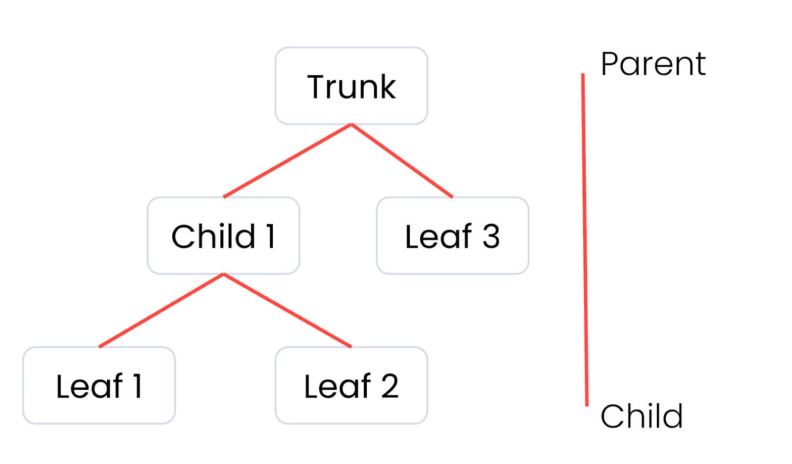
The important detail here is that it’s also hierarchical. Each tile can have a number of children, creating a tree. The trunk of that tree, the root tile, is typically a much less detailed version of the data, and the leaves of that tree, the final child tiles, contain the fully detailed version of the data.
Our ultimate goal here is to strike the perfect balance between performance and visual quality. If we display too many tiles with too much detail, we’ll likely waste a lot of processing power drawing tiny details, often smaller than a single pixel, that the user can’t actually see. That results in unhappy users with slow performing computers and, if they’re on a portable device, they’ll be running out of battery very quickly. On the other hand, if we display too few tiles instead, there will be visible errors on the screen that have users losing confidence in the accuracy of what we’re showing them.
Geometric Error to the rescue
Fortunately, geometric error exists to provide a metric for determining which tiles to display at any given time. We can do so by converting it into a screen-space error in pixels based on the camera’s position. That’ll tell us whether the error would be visible to the end user, but how that’s done is a topic for another blog post. For example, if our geometric error converts to a screen-space error of less than one from the current camera position, we can assume any errors introduced are smaller than a pixel and thus not perceptible.
So what actually is geometric error? At the time of writing, the spec describes it like so:
The geometric error is formulated based on a metric like point density, mesh or texture decimation, or another factor specific to that tileset. In general, a higher geometric error means a tile will be refined more aggressively, and children tiles will be loaded and rendered sooner. Source
Equally, a google search or nowadays AI summary, will point you at some commonly accepted wisdom, sourced from either an old Cesium community thread, or Cesium Github issue:
The geometric error can be computed however you like, but often a good estimate is finding the diagonal of the largest building/feature in the tile. In tileset.json a tile's geometric error will often equal the largest geometric error of its children. Typically leaf tiles have a geometric error of 0. Source
It sounds like it’s really up to us when it comes to defining or calculating it.
Defining Geometric Error
Intuitively, if the objective of geometric error is to understand when the user might be able to detect that some data has been simplified or sampled, we can likely define it as the worst deviation between the two. That might look something like the following for a graphics classic, the Utah teapot.
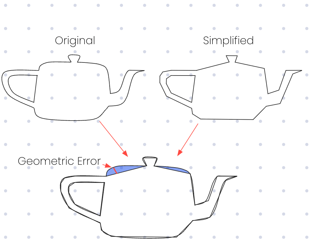
If we were to display the teapot, we can visually see the largest ‘gap’ exists in one of the shaded blue regions, and within those regions the red line indicates the value that intuitively is the point where the two versions of the model are furthest apart.
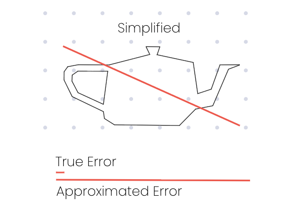
Comparing that to the diagonal approximation we found earlier and we can see that we’re a long way off what feels like the true value:
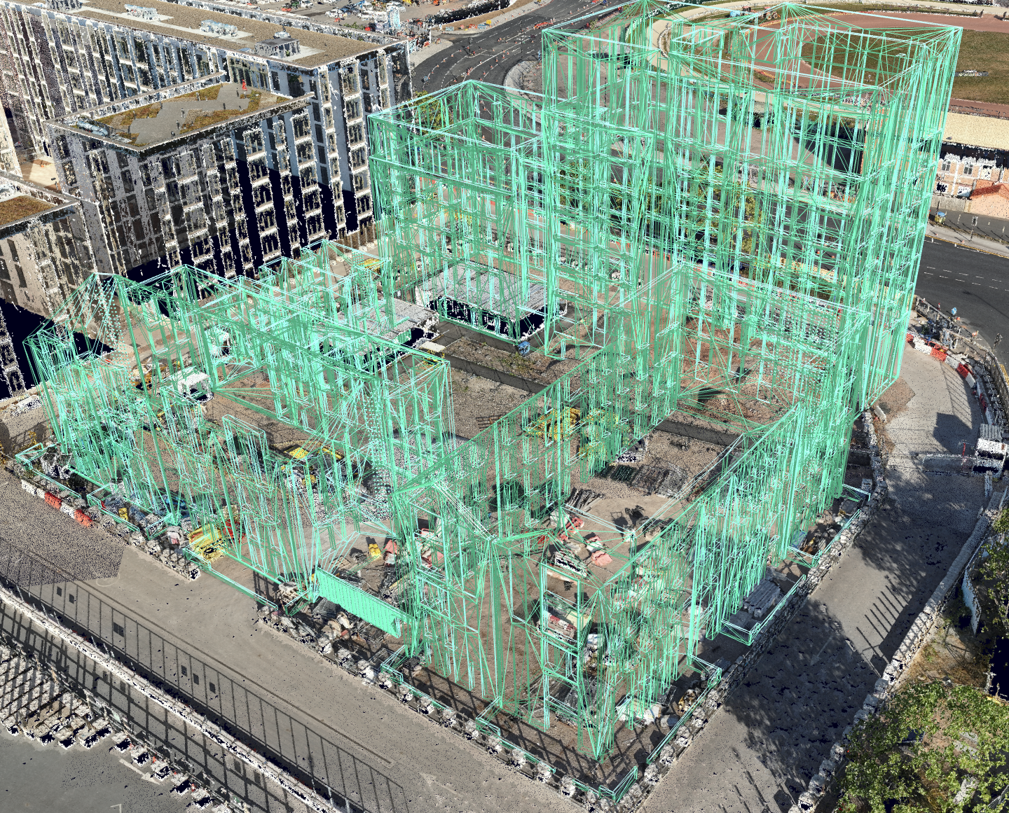
What’s surprising is that despite the glaring difference between these values, it looks correct. If we pass a building model with this approximation into our visualisation engine alongside a photogrammetry scan of the surrounding area for scale, we get the following:
A lesson in overdraw
That looks perfect, so we should just use the approximation, right? Not so fast. Remember the issue we mentioned earlier, in this case we’re rendering the leaf tiles almost exclusively, no matter how far away the camera is. That means we’re rendering the entire model in full detail even when we’re at the point where the whole model occupies just a handful of pixels on the screen.
If we take a look at the wireframe, we can see that this model is actually composed of a surprising number of triangles for its apparent complexity. Those with experience in graphics processing might be reminded of the large amounts of overdrawing when a GPU is asked to draw lots of tiny triangles.
As a large-scale visualisation platform, we often have to display many complex tilesets alongside one another. Trying to do so while rendering only leaf tiles would make the platform very slow and drain user’s batteries very quickly, particularly on mobile devices.
Experimenting with different algorithms
In our time researching, we’ve experimented with many different algorithms. If an algorithm tended to overestimate the true error, we’d end up degrading performance like shown above. Other times, an algorithm might underestimate the true error.
One such case of underestimation came from an attempt to determine the true error based on metrics that came back from our geometry simplification engine. That engine is responsible for creating the less detailed versions of files that customers upload to our platform, so surely it should have all the information about how that error was calculated, right? Again, it’s unfortunately not that simple, and it often ended up with lesser detailed models being selected too quickly.
In the industry we call this LOD (level of detail) pop-in, and you’ve probably seen it before if you’ve ever played a video game. If you want to risk ruining your experience, next time you play, have a look at the details in the distance, moving toward them slowly and you might see things jump around or ‘pop’ in out of nowhere as you cross a distance threshold.
In our case, we can see the building degrading into some kind of deformed rubble as we zoom out, not a good look!
.gif)
How we finally cracked it
Eventually we settled on an algorithm that looks to provide a very accurate result, at the cost of some offline processing time when a user uploads a model. For the maths nerds, it’s a directed hausdorff distance calculation from the surface of a leaf tile to the surface of all of its parent tiles.
That’s a very fancy way of saying, find the red line in the original Utah teapot diagram above. Effectively, we want to iterate through all of the points on the leaf (unsimplified) tile and find its nearest point on the parent (simplified) tile. The furthest of these distances will always be the red line.
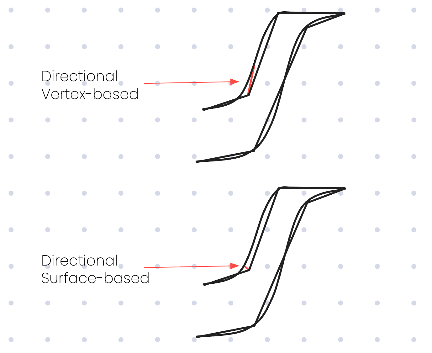
Implementing this gets quite computationally expensive, and we had seen some previous attempts by others which did so by comparing all of the vertices in each model, but that gets really expensive really quickly. To do this properly you also need to compare all of the vertices in both directions, from child to parent and parent to child, further increasing the amount of computation. Instead, we built a surface-based system that overcomes this while only having to compare in one direction.
If we don’t compare in both directions, we’ll end up selecting a value that is much larger than the true value in some cases. If we return to our Utah teapot, we can see one such example when traversing from a leaf vertex to the closest parent vertex.
Announcing Tessera
All this research and experimentation led to us building Tessera. Written in Rust, it’s a blazingly-fast (sorry) implementation of the aforementioned algorithm. We’ve begun using it to reprocess tilesets both new and old to hit that perfect balance between visual quality and performance.
Having such fine-grained control over the detail displayed in models also provides big wins for lower-powered and smaller screen devices. For example, we can adjust the allowable error depending on the pixel density of the user’s screen.
.gif)
We’re not finished yet, but we’ve built a baseline that we’re happy with and it's provided some impressive results. We wanted to share our win with the community that built the foundation upon which we’re standing, so we’re also open sourcing it! If you’re also building stuff with 3D Tiles, whether for production or your own personal projects, we’re providing our implementation under the MIT licence.
You can find the repository on GitHub.